


Cartographical Symbol Construction with MapServer
- Author:
Peter Freimuth
- Contact:
pf at mapmedia.de
- Author:
Arnulf Christl
- Author:
Håvard Tveite
Abstract
This Document refers to the syntax of map and symbol files for MapServer 6. The first version of the document was based on the results of a project carried out at the University of Hannover, Institute of Landscape and Nature Conservation, in 2004, using MapServer 4. It was initiated by Mr. Dipl. Ing. Roland Hachmann. Parts have been taken from a study carried through by Karsten Hoffmann, student of Geography and Cartography at the FU Berlin. In the context of a hands-on training in the company GraS GmbH, Mr. Hoffman mainly dealt with the development of symbols. (Download study report in German) His degree dissertation will also concern this subject.
The document has been heavily revised for MapServer 6.
Tip
All of the mapfiles, symbol files, reports, etc. originally used to produce this document are still available for download (you will have to update them for recent MapServer versions, but they are still very helpful): 1) mapfiles & symbol files, 2) research report (in German), and 3) future improvements (in German).
Introduction
A map is an abstract representation that makes use of point, line and area symbols. Bertin (1974) created a clear and logical symbol scheme in which symbols can be varied referring to graphical variables. The following graphical variables can be used within MapServer: FORM, SIZE, PATTERN, COLOR and LIGHTNESS. Point and area symbols as well as text fonts (ttf) can additionally be displayed with a frame which we call OUTLINE.
The following figure shows the theoretical structure of cartographical symbols, which is also used in MapServer:
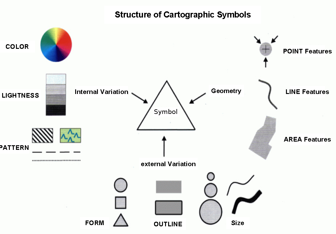
Structure of Cartographical Symbols`
Multiple Rendering and Overlay
Say you want to display a highway with a black border line, two yellow lanes and a red center lane. This calls for a combination of signatures.
Complex cartographical effects can be achieved by rendering the same vector data with different symbols, sizes and colours on top of each other. This can be done using separate LAYERs. This could, however, have performance effects for the application, as every rendering process of the same geometry will take up additional processor time. The preferred solution is to use multiple STYLEs to create complex symbols by overlay.
To create the highway symbol mentioned above with a total width of 9 units, the lowest STYLE (in drawing order) will be a broad black line with a width of 9 units. The second level STYLE will be a yellow line with a width of 7 units, and the topmost STYLE will be a red line with a width of 1 unit. That way each yellow coloured lane will have a width of (7-1)/2 = 3 units.
Combining symbols can be a solution for many kinds of cartographical questions. A combination of different geometry types is also possible. A polygon data set can be rendered as lines to frame the polygons with a line signature. It can also be rendred as polygons with a symbol filling the polygon. When the polygon fill is rendered on top of the lines, the inner part of the underlying outline is covered by the fill symbol of the polygon. What is observed here is a clipping effect that will result in an asymmetric symbol for the boundary line. To present the outline without clipping, just reorder the LAYERs or STYLEs and put the outline presentation on top of the fill.
Yet another way to construct advanced line signatures for framed polygons is to tamper with the original geometries by buffering or clipping the original geometry such that the new objects lie inside the original polygons or grow over the borders. PostGIS can help achieve a lot of effects.
The OPACITY parameter of LAYER and STYLE can be used to achieve transparency (making lower symbols "shine" through upper symbols).
Symbol Scaling
There are two basically different ways of handling the display size of symbols and cartographical elements in a map at different scales. The size of cartographical elements is either set in screen pixels or in real world units.
If the size is set in real world units (for example meters), the symbol will shrink and grow according to the scale at which the map is displayed.
If the size is set in screen pixels, symbols look the same at all scales.
The default behaviour of MapServer is to implement the "screen pixels" size type for displaying cartographical elements.
"Real world units", as described above, can be achieved using either the SIZEUNITS or the SYMBOLSCALEDENOM parameter of the LAYER.
When SIZEUNITS is set (and is not pixels), symbol sizes are specified in real world units (for instance meters). For available units, see the SIZEUNIT documentation.
When SYMBOLSCALEDENOM is set, the given symbols size is used for the map scale 1:SYMBOLSCALEDENOM, for other scales, the symbols are scaled proportionally.
STYLE MAXSIZE and MINSIZE limits the scaling of symbols.
MapServer and symbol specification
In a MapServer application, SYMBOL parameters are organised in the map file as follows:
Each LAYER has a TYPE parameter that defines the type of geometry (point, line or polygon). The symbols are rendered at points, along lines or over areas accordingly.
Basic symbols are defined in SYMBOL elements, using the parameters TYPE, POINTS, IMAGE, FILLED, ANCHORPOINT and more (SYMBOL elements can be collected in separate symbol files for reuse).
Colour, lightness, size and outline are defined inside the STYLE sections of a CLASS section using the parameters COLOR, SIZE, WIDTH and OUTLINECOLOR.
Patterns for styling lines and polygons are defined in STYLE sections using GAP and PATTERN.
Several basic elements can be combined to achieve a complex signature using several STYLEs inside one CLASS.
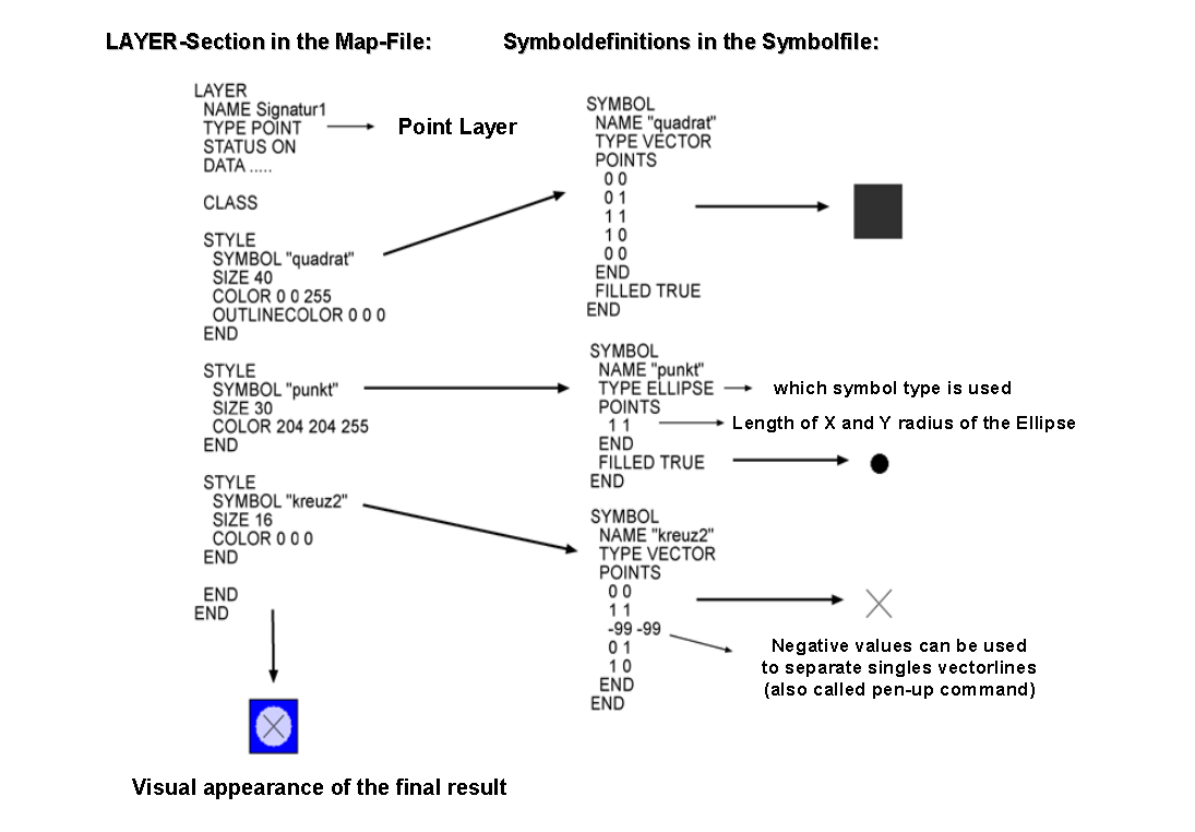
The following example shows the interaction of some of these elements and explains the configuration in the LAYER and the SYMBOL sections necessary for rendering a cartographical point symbol (a red square with a 1 pixel wide black outline and a smaller blue circle inside):

The generated overlay symbol
LAYER section of the map file |
SYMBOL (from a separate symbol file or in-line in the map file) |
|---|---|
# Start of layer definition
LAYER
  # Name of the layer
  NAME "mytest"
  TYPE POINT     # Point geometries
  STATUS DEFAULT # Always draw
  # Use the dataset test.shp
  DATA test
  # Start of a Class definition
  CLASS
    # Start of the first Style
    STYLE
      # Symbol to be used (reference)
      SYMBOL "square"
      # Size of the symbol in pixels
      SIZE 16
      # Colour (RGB) - red
      COLOR 255 0 0
      # Outline colour (RGB) - black
      OUTLINECOLOR 0 0 0
    END # end of STYLE
    # Start of the second Style
    STYLE
      # Symbol to be used (reference)
      SYMBOL "circle"
      # Size of the symbol in pixels
      SIZE 10
      # Colour (RGB) - blue
      COLOR 0 0 255
    END # end of STYLE
  END # end of CLASS
END # end of LAYER
|
# Start of symbol definition
SYMBOL
  # Symbol name (referenced in STYLEs)
  NAME "square"
  TYPE vector # Type of symbol
  # Start of the symbol geometry
  POINTS
    0 0
    0 1
    1 1
    1 0
    0 0
  END # end of POINTS
  # The symbol should be filled
  FILLED true
  # Place the according to its center
  ANCHORPOINT 0.5 0.5
END # end of SYMBOL

# Start of symbol definition
SYMBOL
  # Symbol name (referenced in STYLEs)
  NAME "circle"
  TYPE ellipse # Type of symbol
  # Start of the symbol geometry
  POINTS
    1 1
  END # end of POINTS
  # The symbol should be filled
  FILLED true
  # Place the according to its center
  ANCHORPOINT 0.5 0.5
END # end of SYMBOL
|
Using Cartographical Symbols in MapServer
Vectors, truetype fonts and raster images are basic graphical elements that are defined by the TYPE parameter in the STYLE element. This and the following sections explain how these elements can be combined to create complex cartographical symbols, and they describes some other important aspects of map rendering in MapServer .
Output formats
MapServer support raster output formats (e.g. PNG, JPEG and GIF) and vector output formats (e.g. PDF, SVG). The raster formats (except for GIF) use anti-aliasing. See OUTPUTFORMAT (and MAP IMAGETYPE) for more.
Symbol units
The units used for specifying dimensions is defined in the SIZEUNITS parameter of the LAYER. The available units are listed there. The default unit is pixels.
The MAP element's RESOLUTION and DEFRESOLUTION parameters will determine the resolution of the resulting map and hence the size in pixels of the symbols on the map. DEFRESOLUTION is by default 72 dpi (dots per inch). If RESOLUTION is set to 144 (and DEFRESOLUTION is 72), all dimensions specified in the map file will be multiplied by 144/72 = 2. This can be used to produce higher resolution images.
Dimensions can be specified using decimals.
Scaling of Symbols
The SYMBOLSCALEDENOM parameter in the LAYER section specifies the scale at which the symbol or text label is displayed in exactly the dimensions defined in the STYLEs (for instance using SIZE and WIDTH). Observe that all the parameters concerned with the symbol dimensions (SIZE, WIDTH, ...) are tightly connected to the SYMBOLSCALEDENOM parameter. The MAXSIZE and MINSIZE parameters inside the STYLE element limit the scaling of symbols to the maximum and minimum size specified here (but does not affect the size calculations).
When symbols are scaled as the scale changes, the elements (defined in STYLEs) of a composite cartographical symbol may change their positions relative to each other. This is due to rounding effects when creating the image. The effect is most noticeable at small scales (large scale denominators), when the symbols get small. Due to the same effects, symbols can also slightly change their shape when they get small.
It is not possible to define the display intervals with MINSCALEDENOM and MAXSCALEDENOM in the STYLE-section, so this kind of tuning has to be solved at the LAYER level. To do this, create several LAYERs with the same geometries for different scale levels.
Always observe that cartographical symbols depend a lot on the scale! So be careful with the interaction of content, symbols and scale. All three parameters heavily interact and have to be coordinated to produce a good map.
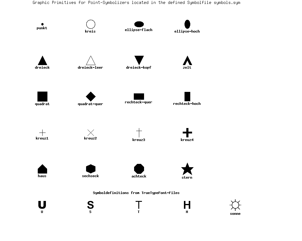
Construction of Point Symbols
In the figure below, point symbols of TYPE truetype, pixmap, ellipse and vector are demonstrated. The precise position of the point for which the symbol is rendered is shown with a small red dot. A small blue dot is used to show an offset position.
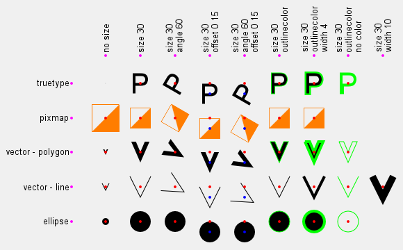
Basic point symbol TYPEs, showing effects of size, offset, angle and outlinecolor
All point symbols can be rotated using the ANGLE parameter.
Since version 6.2, the anchor point / reference point of all point symbols can be set using the SYMBOL ANCHORPOINT parameter. The default anchorpoint is at the center of the boundingbox of the symbol (ANCHORPOINT 0.5 0.5).
Symbols of TYPE vector and ellipse
For symbols of TYPE vector and ellipse the shape of the symbol by setting X and Y values in a local two dimensional coordinate system with X values increasing to the right and Y values increasing downwards. The coordinates defining the symbol is listed in the POINTS parameter, which is explicitly ended using END. Negative values should not be used.
TYPE ellipse is used to create ellipses (and circles). The shape of the ellipse is defined in the POINTS parameter (X - size in the horizontal direction, Y - size in the vertical direction). To create a circle, let X and Y have the same value.
TYPE vector is used to define advanced vector symbols. The shape of the symbol is defined in the POINTS parameter. A vector symbol can consist of several elements. The coordinates -99 -99 are used to separate the elements.
To create a polygon vector symbol, the SYMBOL FILLED parameter must be set to true. If the end point is not equal to the start point of a polygon geometry, it will be closed automatically.
The maximum number of points is 100, but this can be increased by changing the parameter MS_MAXVECTORPOINTS in the file mapsymbols.h before compilation.
When creating symbols of TYPE vector you should observe some style guidelines.
Avoid downtilted lines in area symbols, as they will lead to heavy aliasing effects.
Do not go below a useful minimum size. This is relevant for all types of symbols.
Keep in mind that for pixel images, every symbol of TYPE vector has to be rendered using pixels.
注釈
The bounding box of a vector symbol has (0,0) in the symbol coordinate system as its upper left corner. This can be used to precisely control symbol placement. Since version 6.2 SYMBOL ANCHORPOINT should be used instead.
Symbols of TYPE truetype
You can use symbols from truetype fonts. The symbol settings are defined in the SYMBOL element. Specify the character or the ASCII number of the character to be used in the CHARACTER parameter. The FONT parameter is used to specify the font to be used (the alias name from the font file - often "fonts.list"). The FONTSET parameter of the MAP element must be set for fonts to work.
For gif output (GD renderer), you can define that you want to apply antialiasing to the characters by using the parameter ANTIALIAS. It is recommended to do this especially with more complex symbols and whenever they don't fit well into the raster matrix or show a visible pixel structure.
Colours for truetype symbols can be specified in LAYER CLASS STYLE (as with symbols of the TYPE vector and ellipse). You can specify both fill colour and outline colour.
To find out the character number of a symbol use one of the following options:
Use the software FontMap (Shareware, with free trial version for download, thanks Till!).
Use the MS Windows truetype map.
Trial and Error. :-)
Please note that the numbering of the so-called "symbol fonts" starts at 61440! So if you want to use character T, you have to use 61440 + 84 = . (ain't that a pain!!)
You can also place truetype characters and strings on the map using LABEL. Then you can control the placing of the text by using the POSITION parameter [ul|uc|ur|cl|cc|cr|ll|lc|lr], that specifies the position relative to the geometric origin of the geometry.
Symbols of TYPE pixmap
Symbols of the TYPE pixmap are simply small raster images. The file name of the raster image is specified in the IMAGE parameter of the SYMBOL element. MapServer supports the raster formats GIF and PNG for pixmaps.
Observe the colour depth of the images and avoid using 24 bit PNG symbols displayed in 8 bit mode as this may cause unexpected colour leaps.
When using raster images, the colour cannot be modified in the SYMBOL element subsequently.
You can specify a colour with the TRANSPARENT parameter which will not be displayed - i.e. it will be transparent. As a result, underlying objects and colours are visible.
The SIZE parameter defines the height of pixmap symbols when rendered. The pixel structure will show when the SIZE grows too large. If you are using symbol scaling (LAYER SYMBOLSCALEDENOM is set or LAYER SIZEUNITS is not pixels) and want to prevent this from happening, you should set the STYLE MAXSIZE parameter.
Symbol definitions for the figure that demonstrates point symbols
This code was used to produce the symbols in the point symbol figure.
First, the symbol definitions:
SYMBOL
  NAME "o-flag-trans"
  TYPE pixmap
  IMAGE "o-flag-trans.png"
END # SYMBOL

SYMBOL
  NAME "circlef"
  TYPE ellipse
  FILLED true
  POINTS
    10 10
  END # POINTS
END # SYMBOL

SYMBOL
  NAME "P"
  TYPE truetype
  FONT "arial"
  CHARACTER "P"
END # SYMBOL

SYMBOL
  NAME "v-line"
  TYPE vector
  FILLED false
  POINTS
    0  0
    5  10
    10 0
  END # POINTS
END # SYMBOL

SYMBOL
  NAME "v-poly"
  TYPE vector
  FILLED true
  POINTS
    0  0
    3.5 8
    7 0
    5.2 0
    3.5 4
    1.8 0
    0 0
  END # POINTS
END # SYMBOL
Then, the LAYERs and STYLEs used for producing the polygon V symbols in the point symbol figure:
LAYER  # Vector v - polygon
  STATUS DEFAULT
  TYPE POINT
  FEATURE
    POINTS
      10 30
    END # Points
  END # Feature
  CLASS
    STYLE
      SYMBOL "v-poly"
      COLOR 0 0 0
    END # STYLE
    STYLE
      SYMBOL "circlef"
      COLOR 255 0 0
      SIZE 4
    END # STYLE
  END # CLASS
END # LAYER

LAYER  # Vector v - polygon, size
  STATUS DEFAULT
  TYPE POINT
  FEATURE
    POINTS
      20 30
    END # Points
  END # Feature
  CLASS
    STYLE
      SYMBOL "v-poly"
      COLOR 0 0 0
      SIZE 30
    END # STYLE
    STYLE
      SYMBOL "circlef"
      COLOR 255 0 0
      SIZE 4
    END # STYLE
  END # CLASS
END # LAYER

LAYER  # Vector v - polygon, size, angle
  STATUS DEFAULT
  TYPE POINT
  FEATURE
    POINTS
      30 30
    END # Points
  END # Feature
  CLASS
    STYLE
      SYMBOL "v-poly"
      COLOR 0 0 0
      SIZE 30
      ANGLE 60
    END # STYLE
    STYLE
      SYMBOL "circlef"
      COLOR 255 0 0
      SIZE 4
    END # STYLE
  END # CLASS
END # LAYER

LAYER  # Vector v - polygon, size, offset
  STATUS DEFAULT
  TYPE POINT
  FEATURE
    POINTS
      40 30
    END # Points
  END # Feature
  CLASS
    STYLE
      SYMBOL "v-poly"
      COLOR 0 0 0
      SIZE 30
      OFFSET 0 15
    END # STYLE
    STYLE
      SYMBOL "circlef"
      COLOR 255 0 0
      SIZE 4
    END # STYLE
  END # CLASS
END # LAYER

LAYER  # Vector v - polygon, size, angle, offset
  STATUS DEFAULT
  TYPE POINT
  FEATURE
    POINTS
      50 30
    END # Points
  END # Feature
  CLASS
    STYLE
      SYMBOL "v-poly"
      COLOR 0 0 0
      SIZE 30
      ANGLE 60
      OFFSET 0 15
    END # STYLE
    STYLE
      SYMBOL "circlef"
      COLOR 255 0 0
      SIZE 4
    END # STYLE
  END # CLASS
END # LAYER

LAYER  # Vector v - polygon, size outline
  STATUS DEFAULT
  TYPE POINT
  FEATURE
    POINTS
      60 30
    END # Points
  END # Feature
  CLASS
    STYLE
      SYMBOL "v-poly"
      COLOR 0 0 0
      SIZE 30
      OUTLINECOLOR 0 255 0
    END # STYLE
    STYLE
      SYMBOL "circlef"
      COLOR 255 0 0
      SIZE 4
    END # STYLE
  END # CLASS
END # LAYER

LAYER  # Vector v - polygon, size, outline, width
  STATUS DEFAULT
  TYPE POINT
  FEATURE
    POINTS
      70 30
    END # Points
  END # Feature
  CLASS
    STYLE
      SYMBOL "v-poly"
      COLOR 0 0 0
      SIZE 30
      OUTLINECOLOR 0 255 0
      WIDTH 4
    END # STYLE
    STYLE
      SYMBOL "circlef"
      COLOR 255 0 0
      SIZE 4
    END # STYLE
  END # CLASS
END # LAYER

LAYER  # Vector v - polygon, size, outline, no color
  STATUS DEFAULT
  TYPE POINT
  FEATURE
    POINTS
      80 30
    END # Points
  END # Feature
  CLASS
    STYLE
      SYMBOL "v-poly"
      SIZE 30
      OUTLINECOLOR 0 255 0
    END # STYLE
    STYLE
      SYMBOL "circlef"
      COLOR 255 0 0
      SIZE 4
    END # STYLE
  END # CLASS
END # LAYER
Combining symbols
The following figure shows how to combine several basic symbols to create a complex point symbol. The combination is achieved by adding several STYLEs within one LAYER. Each STYLE element references one SYMBOL element. All the basic symbols are centered and overlaid when rendered.
Notice that the SIZE parameter in the STYLE element refers to the height of the symbol (extent in the Y direction). A standing rectangle will thus display with a smaller area than a lying rectangle, although both have the same SIZE parameter and the same maximum Y value in the SYMBOL element. When combining several basic point symbols on top of each other, they will not always be centered correctly due to the integer mathematics required when rendering raster images. It is recommended not to combine elements with even and odd numbered SIZE parameters, as this tends to produce larger irregularities.
Construction of Point Symbols
Construction of Line Symbols
For displaying line geometries, you specify the width of the lines using the WIDTH parameter and the colour using the COLOR parameter. If no colour is specified, the line will not be rendered. If no width is specified, a thin line (one unit (pixel) wide) will be rendered. The LINECAP, LINEJOIN and LINEJOINMAXSIZE parameters are used to specify how line ends and corners are to be rendered.
Overlaying lines
When combining several styles / symbols on a line, they will be positioned on the baseline which is defined by the geometry of the object. In most cases MapServer correctly centers symbols. The combination of a line displayed in 16 units width and overlaid with a 10 unit width line, results in a line symbol with a 3 unit border. If the cartographical symbol is to contain a centered line with a width of 1 pixel, then the widths should be reconfigured, for example to 11 and 17 units. As a rule of thumb don't combine even numbered and odd numbered widths.
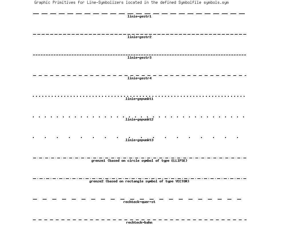
Use of the PATTERN and GAP parameters
The PATTERN and GAP parameters can be used to produce styled lines in MapServer.
To create line patterns, use the PATTERN parameter of the STYLE. Here you define dashes by specifying the length of the first dash, followed by the length of the first gap, then the length of the second dash, followed by the second gap, and so on. This pattern will be repeated as many times as that pattern will fit into the line. LINECAP can be used to control how the ends of the dashes are rendered. LINEJOIN can be used to control how sharp bends are rendered. In the left column of the figure, you will find three examples where PATTERN has been used. Number 2 from below uses LINECAP butt, number 3 from below uses LINECAP round (and LINEJOIN miter) and number 4 from below uses LINECAP butt (and is overlaid over a wider, dark grey line). To produce dots, use 0 for dash length with LINECAP 'round'.
Styled lines can be specified using GAP and a symbol for styling. In the figure, you will find examples where GAP has been used (in the right column). At the bottom a SYMBOL of TYPE ellipse has been used, then a SYMBOL of TYPE vector, then a SYMBOL of TYPE font and then a SYMBOL of TYPE pixmap. To control the placement of the symbols relative to the line (to get asymmetrical styling), use SYMBOL ANCHORPOINT (as explained later).
注釈
Since version 6.2 it is possible to specify an offset (start gap) when creating asymmetrical patterns using the STYLE INITIALGAP parameter. INITIALGAP can be used with GAP and with PATTERN.
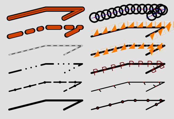
The following figure shows how to use styles to define different kinds of line symbols.
PATTERN usage is demonstrated in the 2nd, 3rd, 4th and 5th symbol from the bottom in the left column.
GAP usage is demonstrated in the 2nd symbol from the bottom in the left column and all the symbols in the right column.
negative GAP value usage is demonstrated in the all the symbols in the right column, except for the one at the bottom.
INITIALGAP usage is demonstrated in the 2nd and 5th symbol from the bottom in the left column.
STYLE OFFSET usage is demonstrated in the 5th symbol from the bottom in the right column
Construction of Line Symbols
Below you will find the SYMBOLs and STYLEs that were used to produce the line symbols in "Construction of Line Symbols". The LAYERs are ordered from bottom to top of the figure.
Styles and symbols for lines
SYMBOL
  NAME "circlef"
  TYPE ellipse
  FILLED true
  POINTS
    1 1
  END # POINTS
END # SYMBOL

SYMBOL
  NAME "P"
  TYPE truetype
  FONT "arial"
  CHARACTER "P"
END # SYMBOL

SYMBOL
  NAME "vertline"
  TYPE vector
  FILLED true
  POINTS
    0 0
    0 10
    2.8 10
    2.8 0
    0 0
  END # POINTS
  ANCHORPOINT 0.5 0
END # SYMBOL

SYMBOL
  NAME "o-flag-trans"
  TYPE pixmap
  IMAGE "o-flag-trans.png"
END # SYMBOL

######## Left column ###############

LAYER  # Simple line
  STATUS DEFAULT
  TYPE LINE
  FEATURE
    POINTS
      5 5
      25 10
      45 10
      35 5
    END # Points
  END # Feature
  CLASS
    STYLE
      COLOR 0 0 0
      WIDTH 6.5
    END # STYLE
  END # CLASS
END # LAYER

LAYER  # Dashed line with symbol overlay
  STATUS DEFAULT
  TYPE LINE
  FEATURE
    POINTS
      5 15
      25 20
      45 20
      35 15
    END # Points
  END # Feature
  CLASS
    STYLE
      COLOR 0 0 0
      WIDTH 5.0
      PATTERN 40 10 END
    END # STYLE
    STYLE
      SYMBOL "circlef"
      COLOR 0 0 0
      SIZE 8
      INITIALGAP 20
      GAP 50
    END
  END # CLASS
END # LAYER

LAYER  # Dashed line, varying
  STATUS DEFAULT
  TYPE LINE
  FEATURE
    POINTS
      5 25
      25 30
      45 30
      35 25
    END # Points
  END # Feature
  CLASS
    STYLE
      COLOR 0 0 0
      WIDTH 5.0
      LINECAP round #[butt|round|square|triangle]
      LINEJOIN miter #[round|miter|bevel]
      LINEJOINMAXSIZE 3
      PATTERN 40 17 0 17 0 17 0 17 END
    END # STYLE
  END # CLASS
END # LAYER

LAYER  # Line dash overlay
  STATUS DEFAULT
  TYPE LINE
  FEATURE
    POINTS
      5 35
      25 40
      45 40
      35 35
    END # Points
  END # Feature
  CLASS
    STYLE
      COLOR 102 102 102
      WIDTH 4.0
    END # STYLE
    STYLE
      COLOR 255 255 255
      WIDTH 2.0
      LINECAP BUTT
      PATTERN 8 12 END
    END # STYLE
  END # CLASS
END # LAYER

LAYER  # Line dashed with dashed overlay
  STATUS DEFAULT
  TYPE LINE
  FEATURE
    POINTS
      5 45
      25 50
      45 50
      35 45
    END # Points
  END # Feature
  CLASS
    STYLE
      COLOR 0 0 0
      WIDTH 16.0
      PATTERN 40 20 20 20 10 20 END
    END # STYLE
    STYLE
      COLOR 209 66 0
      WIDTH 12.0
      INITIALGAP 2
      PATTERN 36 24 16 24 6 24 END
    END # STYLE
  END # CLASS
END # LAYER

LAYER  # Line overlay - 3
  STATUS DEFAULT
  TYPE LINE
  FEATURE
    POINTS
      5 55
      25 60
      45 60
      35 55
    END # Points
  END # Feature
  CLASS
    STYLE
      COLOR 0 0 0
      WIDTH 17.0
    END # STYLE
    STYLE
      COLOR 209 66 0
      WIDTH 11.0
    END # STYLE
    STYLE
      COLOR 0 0 0
      WIDTH 1.0
    END # STYLE
  END # CLASS
END # LAYER

######## right column ############

LAYER  # Line - ellipse overlay
  STATUS DEFAULT
  TYPE LINE
  FEATURE
    POINTS
      50 5
      70 10
      90 10
      80 5
    END # Points
  END # Feature
  CLASS
    STYLE
      COLOR 0 0 0
      WIDTH 3.6
    END # STYLE
    STYLE
      COLOR 0 0 0
      SYMBOL "circlef"
      SIZE 10
      GAP 42
    END # STYLE
    STYLE
      COLOR 255 0 0
      SYMBOL "circlef"
      SIZE 3
      GAP 42
    END # STYLE
  END # CLASS
END # LAYER

LAYER  # Line - symbol overlay
  STATUS DEFAULT
  TYPE LINE
  FEATURE
    POINTS
      50 15
      70 20
      90 20
      80 15
    END # Points
  END # Feature
  CLASS
    STYLE
      COLOR 0 0 0
      WIDTH 2.8
    END # STYLE
    STYLE
      COLOR 0 0 0
      SYMBOL "vertline"
      SIZE 10.0
      ANGLE 30
      GAP -50
    END # STYLE
    STYLE
      COLOR 255 0 0
      SYMBOL "circlef"
      SIZE 3
      GAP 50
    END # STYLE
  END # CLASS
END # LAYER

LAYER  # Line - font overlay
  STATUS DEFAULT
  TYPE LINE
  FEATURE
    POINTS
      50 25
      70 30
      90 30
      80 25
    END # Points
  END # Feature
  CLASS
    STYLE
      COLOR 0 0 0
      WIDTH 6
    END # STYLE
    STYLE
      COLOR 102 0 0
      SYMBOL "P"
      SIZE 20
      GAP -30
    END # STYLE
    STYLE
      COLOR 255 0 0
      SYMBOL "circlef"
      SIZE 3
      GAP 30
    END # STYLE
  END # CLASS
END # LAYER

LAYER  # Line - pixmap overlay
  STATUS DEFAULT
  TYPE LINE
  FEATURE
    POINTS
      50 35
      70 40
      90 40
      80 35
    END # Points
  END # Feature
  CLASS
    STYLE
      COLOR 0 0 0
      WIDTH 6
    END # STYLE
    STYLE
      COLOR 102 0 0
      SYMBOL "o-flag-trans"
      SIZE 20
      GAP -30
    END # STYLE
    STYLE
      COLOR 255 0 0
      SYMBOL "circlef"
      SIZE 3
      GAP 30
    END # STYLE
  END # CLASS
END # LAYER

LAYER  # Line - pixmap overlay
  STATUS DEFAULT
  TYPE LINE
  FEATURE
    POINTS
      50 45
      70 50
      90 50
      80 45
    END # Points
  END # Feature
  CLASS
    STYLE
      COLOR 0 0 0
      WIDTH 6
    END # STYLE
    STYLE
      COLOR 102 0 0
      SYMBOL "o-flag-trans"
      SIZE 20
      GAP -30
      OFFSET -10 -99
    END # STYLE
    STYLE
      COLOR 255 0 0
      SYMBOL "circlef"
      SIZE 3
      GAP 30
    END # STYLE
  END # CLASS
END # LAYER
LINECAP
By default, all lines (and patterns) will be drawn with rounded ends (extending the lines slightly beyond their ends). This effect gets more obvious the larger the width of the line is. It is possible to alter this behaviour using the LINECAP parameter of the STYLE. LINECAP butt will give butt ends (stops the line exactly at the end), with no extension of the line. LINECAP square will give square ends, with an extension of the line. LINECAP round is the default.
LINEJOIN
The different values for the parameter LINEJOIN have the following visual effects. Default is round. miter will follow line borders until they intersect and fill the resulting area. none will render each segment using linecap butt. The figure below illustrates the different linejoins.
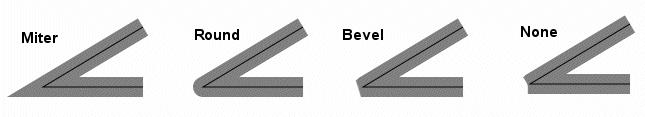
Different kinds of linejoins
LINEJOINMAXSIZE (only relevant for LINEJOIN miter)
Specify the maximum length of miter linejoin factor m (see the figure below). The value is a multiplication factor (default 3).
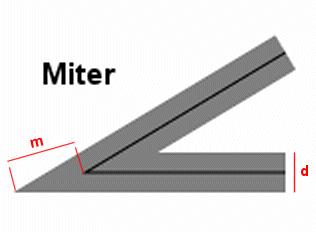
Miter linejoin
The max length of the miter join is calculated as follows (d is the line width, specified with the WIDTH parameter of the STYLE):
m_max = d * LINEJOINMAXSIZE
If m > m_max, then the connection length will be set to m_max.
Use of the OFFSET parameter
In STYLE, an OFFSET parameter can be set to shift symbols in the X and Y direction. The displacement is not influenced by the direction of the line geometry. Therefore the point symbols used for styling are all shifted in the same direction, independent of the direction of the line (as defined in style number 2 in the map file example below - red line in the map image). A positive X value shifts to the right. A positive Y value shifts downwards.
To generate lines that are shifted relative to the original lines, -99 has to be used for the Y value of the OFFSET. Then the X value defines the distance to the line from the original geometry (perpendicular to the line). A positive X value will shift to the right (when viewed in the direction of the line), a negative X value will shift to the left.
The example below shows how OFFSET works with the use of -99 (blue and green lines) and without the use of -99 (red line). The thin black line shows the location of the line geometry.
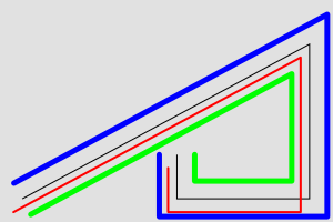
Use of the OFFSET parameter with lines - map image
LAYER  #
  STATUS DEFAULT
  TYPE LINE
  FEATURE
    POINTS
      20 20
      280 160
      280 20
      160 20
      160 60
    END # Points
  END # Feature
  CLASS
    STYLE  # no offset
      COLOR 0 0 0    # black
      WIDTH 1
    END # STYLE
    STYLE  # simple offset left and down
      COLOR 255 0 0  # red
      WIDTH 2
      OFFSET -8 12
    END # STYLE
    STYLE   # left offset rel. to line direction
      COLOR 0 0 255  # blue
      WIDTH 5
      OFFSET -16 -99
    END # STYLE
    STYLE   # right offset rel. to line direction
      COLOR 0 255 0  # green
      WIDTH 5
      OFFSET 16 -99
    END # STYLE
  END # CLASS
END # LAYER
Asymmetrical line styling with point symbols
Line number 2 and 5 from the bottom in the right column of the "Construction of Line Symbols" figure are examples of asymmetrical line styling using a point symbol. This can be achieved either by using an OFFSET (with a Y value of -99), or by using ANCHORPOINT, as described in the tricks section below. Line number 2 from the bottom can be produced using ANCHORPOINT - this is the best method for placing symbols on lines. Line number 5 from the bottom is produced using STYLE OFFSET. As can be seen, the symbols are here rendered on the offset line, meaning that at sharp bends, some symbols will be placed far away from the line.
Area Symbols
Areas (polygons) can be filled with full colour. Areas can also be filled with symbols to create for instance hatches and graticules.
The symbols are by default used as tiles, and rendered (without spacing) one after the other in the x and y direction, filling the whole polygon.
If the SIZE parameter is used in the STYLE, the symbols will be scaled to the specified height.
The GAP parameter of the STYLE can be used to increase the spacing of the symbols.
The AGG renderer uses anti-aliasing by default, so edge effects around the symbols can occur.
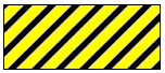
Hatch fill
Simple line hatches (e.g. horizontal, vertical and diagonal) can be created by filling the polygon with a hatch symbol.
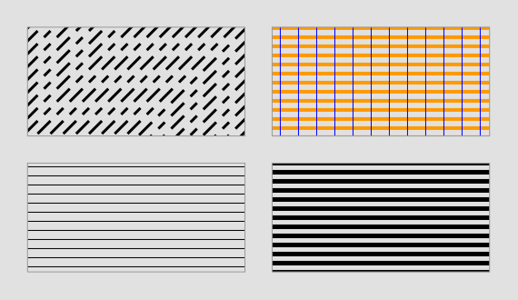
Hatch examples
The SIZE parameter in the STYLE that uses a SYMBOL of type hatch specifies the distance from center to center between the lines (the default is 1). The WIDTH parameter specifies the width of the lines in the hatch pattern (default is 1). The ANGLE parameter specifies the direction of the lines (default is 0 - horizontal lines). Since version 6.2, the PATTERN parameter can be used to create hatches with dashed lines.
The figure demonstrates the use of SIZE (bottom left); WIDTH (bottom right); ANGLE, PATTERN and SIZE (top left); and overlay (top right) of hatches.
The code below shows excerpts of the map file that was used to produce the figure.
First, the SYMBOL definition:
SYMBOL
  NAME "hatchsymbol"
  TYPE hatch
END
Then the CLASS definitions:
LAYER # hatch
    ...
   CLASS
    STYLE
      SYMBOL "hatchsymbol"
      COLOR 0 0 0
      SIZE 10
    END # STYLE
   END # CLASS
  END # LAYER

  LAYER # hatch with angle and pattern
   ...
   CLASS
    STYLE
      SYMBOL "hatchsymbol"
      COLOR 0 0 0
      SIZE 10
      WIDTH 3
      ANGLE 45
      PATTERN 20 10 10 10 END
    END # STYLE
   END # CLASS
  END # LAYER

  LAYER # hatch with wide lines
   ...
   CLASS
    STYLE
      SYMBOL "hatchsymbol"
      COLOR 0 0 0
      SIZE 10
      WIDTH 5
    END # STYLE
   END # CLASS
  END # LAYER

  LAYER # cross hatch
   ...
   CLASS
    STYLE
      SYMBOL "hatchsymbol"
      COLOR 255 153 0
      SIZE 10
      WIDTH 4
    END # STYLE
    STYLE
      SYMBOL "hatchsymbol"
      COLOR 0 0 255
      SIZE 20
      ANGLE 90
    END # STYLE
   END # CLASS
  END # LAYER
Polygon fills with symbols of TYPE pixmap
Polygons can be filled with pixmaps.
注釈
If the STYLE SIZE parameter is different from the image height of the pixmap, there can be rendering artifacts around the pixmaps (visible as a grid with the "background" colour).
Pixmap symbols can be rotated using the ANGLE parameter, but for polygon fills, this produces strange effects, and is not recommended.
To create complex area symbols, e.g. with defined distances between single characters or hatches with broad lines, pixmap fill is probably the best option. Depending on the desired pattern you have to generate the raster image with high precision using a graphical editor. The figure below is an example of how to obtain a regular allocation of symbols with defined spacing.
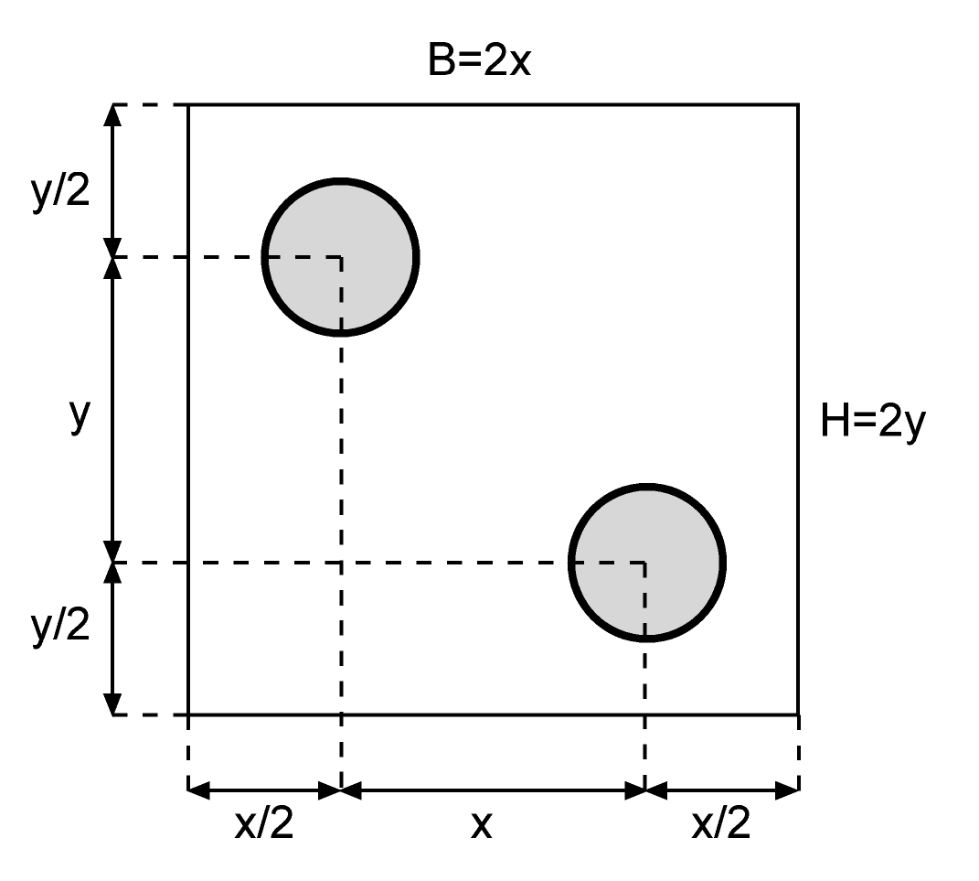
Raster image for a regular symbol fill
You can use other shapes than circles. B defines the width and H the height of the raster image. For a regular arrangement of symbols in a 45 degree angle B = H. For symbols, which are regularly arranged in parallel and without offset between each other one centered symbol with the same x and y distances to the imageborder is enough.
The following figure shows an example of how you can design a pixmap to produce a hatch with wide lines.
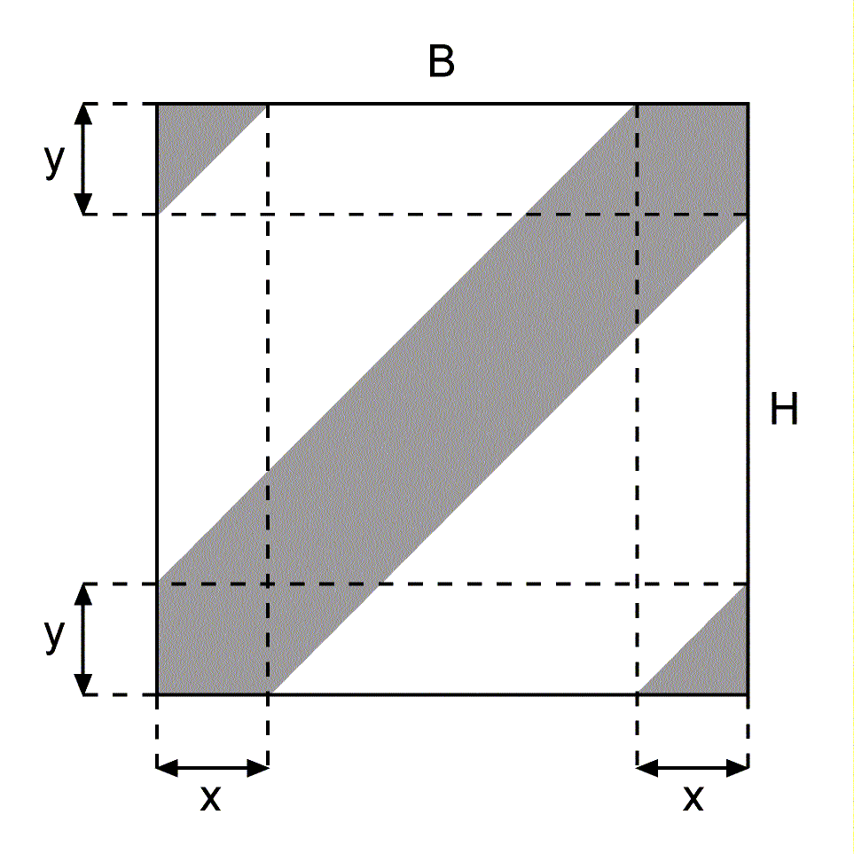
Raster image for a hatched fill
To create a 45 degree hatch use:
B = H and x = y
注釈
When using the MapServer legend, observe that each raster pixmap is displayed only once in the original size in the middle of the legend box.
The example below shows some pixmap symbols which can be used as area symbols with transparency. The raster images were created using FreeHand, finished with Photoshop and exported to PNG with special attention to the colour palette.
CLASS section |
SYMBOL definition |
|---|---|
CLASS
  STYLE
    COLOR 255 255 0
  END
  STYLE
    SYMBOL "in_the_star"
  END
  STYLE
    OUTLINECOLOR 0 0 0
    WIDTH 1
  END
END
|
SYMBOL
  NAME "in_the_star"
  TYPE PIXMAP
  IMAGE "stern.png"
  TRANSPARENT 8
END

|
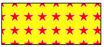
Polygon fill - regular grid pattern
CLASS section |
SYMBOL definition |
|---|---|
CLASS
  STYLE
    SYMBOL "in_point1"
  END
  STYLE
    OUTLINECOLOR 0 0 0
    WIDTH 1
  END
END
|
SYMBOL
  NAME "in_point1"
  TYPE PIXMAP
  IMAGE "flaeche1_1.png"
  TRANSPARENT 13
END

|
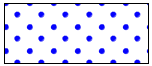
Polygon fill - diagonal pattern
CLASS section |
SYMBOL definition |
|---|---|
CLASS
  STYLE
    COLOR 255 255 0
  END
  STYLE
    SYMBOL "in_hatch"
  END
  STYLE
    OUTLINECOLOR 0 0 0
    WIDTH 1
  END
END
|
SYMBOL
  NAME "in_hatch"
  TYPE PIXMAP
  IMAGE "schraffur.png"
  TRANSPARENT 2
END

|
Polygon fill - hatch
Polygon fills with symbols of TYPE vector
Polygons can be filled with symbols of TYPE vector. As for the other symbol fills, the pattern will be generated by using the specified symbol for the tiles. The bounding box of the symbol is used when tiling.
Creating vector symbols for polygon fills is done in much the same way as for pixmap symbols. Precision is necessary to get nice symmetrical symbols.
The upper left corner of the bounding box of a symbol of TYPE vector is always (0, 0) in the symbol's coordinate system. The lower right corner of the bounding box is determined by the maximum x and y values of the symbol definition (POINTS parameter). The fact that the upper left corner always is at (0,0) makes it convenient to construct symbols such as the dash signature found as number two from the bottom in the centre column of the example below.
Both polygon (FILLED true) and line (FILLED false) vector symbols can be used. For line symbols, the WIDTH parameter of the STYLE will give the line width and the SIZE parameter will specify the height of the symbol.
注釈
For vector line symbols (FILL off), if a width greater than 1 is specified, the lines will grow to extend outside the original bounding box of the symbol. The parts that are outside of the bounding box will be cut away.
STYLE ANGLE can be used for polygon fills, but will only rotate each individual symbol, not the pattern as a whole. It is therefore quite demanding to generate rotated patterns.
Below you will find some examples of vector symbols used for polygon fills. The polygon fill is accompanied by the vector symbol used for the fill. The center of the vector symbol is indicated with a red dot.
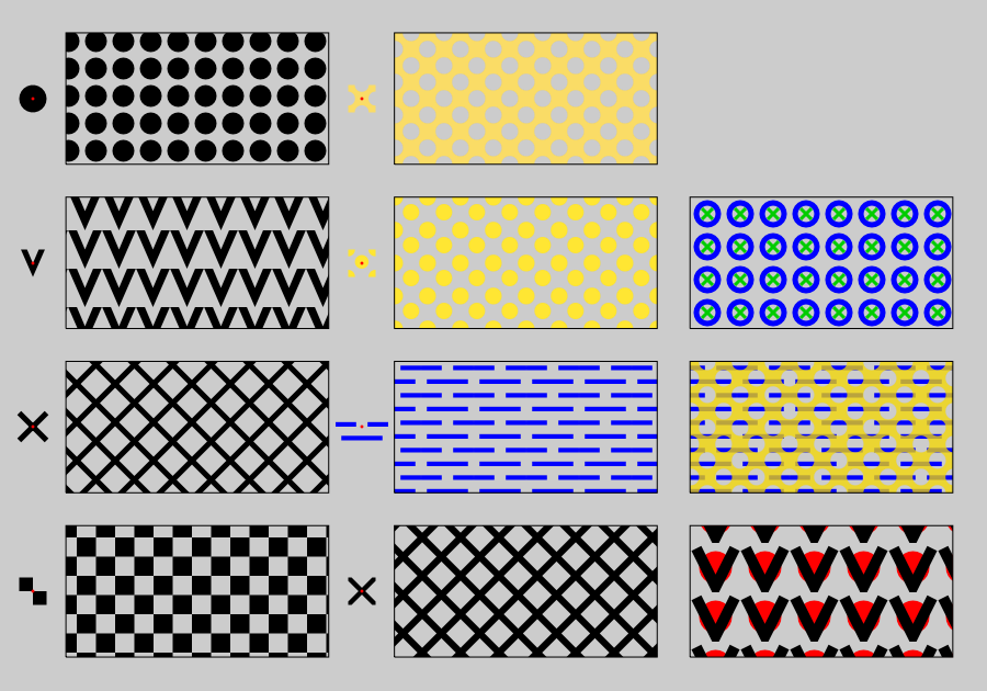
Polygon fills - vector
Excerpts from the map file for the polygon fill vector examples above
First, the LAYERs
LAYER  # chess board
  STATUS DEFAULT
  TYPE POLYGON
  FEATURE
    POINTS
      5 5
      5 25
      45 25
      45 5
      5 5
    END # Points
  END # Feature
  CLASS
    STYLE
      SYMBOL "chess"
      COLOR 0 0 0
      SIZE 35
    END # STYLE
  END # CLASS
END # LAYER

LAYER  # x - line
  STATUS DEFAULT
  TYPE POLYGON
  FEATURE
    POINTS
      5 30
      5 50
      45 50
      45 30
      5 30
    END # Points
  END # Feature
  CLASS
    STYLE
      SYMBOL "x-line"
      COLOR 0 0 0
      WIDTH 5
      SIZE 35
    END # STYLE
  END # CLASS
END # LAYER

LAYER  # v polygon
  STATUS DEFAULT
  TYPE POLYGON
  FEATURE
    POINTS
      5 55
      5 75
      45 75
      45 55
      5 55
    END # Points
  END # Feature
  CLASS
    STYLE
      SYMBOL "v-poly"
      COLOR 0 0 0
      SIZE 35
    END # STYLE
  END # CLASS
END # LAYER

LAYER  # Circles
  STATUS DEFAULT
  TYPE POLYGON
  FEATURE
    POINTS
      5 80
      5 100
      45 100
      45 80
      5 80
    END # Points
  END # Feature
  CLASS
    STYLE
      SYMBOL "circlef"
      COLOR 0 0 0
      SIZE 20
      GAP 25
    END # STYLE
  END # CLASS
END # LAYER

LAYER  # x polygon
  STATUS DEFAULT
  TYPE POLYGON
  FEATURE
    POINTS
      55 5
      55 25
      95 25
      95 5
      55 5
    END # Points
  END # Feature
  CLASS
    STYLE
      COLOR 0 0 0
      SYMBOL "x-poly-fill"
      SIZE 35
    END # STYLE
  END # CLASS
END # LAYER

LAYER  # indistinct marsh
  STATUS DEFAULT
  TYPE POLYGON
  FEATURE
    POINTS
      55 30
      55 50
      95 50
      95 30
      55 30
    END # Points
  END # Feature
  CLASS
    STYLE
      COLOR 0 0 255
      SYMBOL "ind_marsh_poly"
      SIZE 25
    END # STYLE
  END # CLASS
END # LAYER

LAYER  # diagonal circles
  STATUS DEFAULT
  TYPE POLYGON
  FEATURE
    POINTS
      55 55
      55 75
      95 75
      95 55
      55 55
    END # Points
  END # Feature
  CLASS
    STYLE
      COLOR  255 230 51
      SYMBOL "diag_dots"
      SIZE 30
    END # STYLE
  END # CLASS
END # LAYER


LAYER  # diagonal holes in yellow
  STATUS DEFAULT
  TYPE POLYGON
  FEATURE
    POINTS
      55 80
      55 100
      95 100
      95 80
      55 80
    END # Points
  END # Feature
  CLASS
    STYLE
      SYMBOL "diag_holes"
      SIZE 30
      COLOR 250 220 102
    END # STYLE
  END # CLASS
END # LAYER

LAYER  # v line + circle
  STATUS DEFAULT
  TYPE POLYGON
  FEATURE
    POINTS
      100 5
      100 25
      140 25
      140 5
      100 5
    END # Points
  END # Feature
  CLASS
    STYLE
      COLOR 255 0 0
      SYMBOL "circlef"
      SIZE 30
      GAP 45
    END # STYLE
    STYLE
      COLOR 0 0 0
      SYMBOL "v-line"
      LINEJOIN miter
      LINECAP butt
      SIZE 35
      WIDTH 10
      GAP 45
    END # STYLE
  END # CLASS
END # LAYER

LAYER  # indistinct marsh + diagonal holes in yellow
  STATUS DEFAULT
  TYPE POLYGON
  FEATURE
    POINTS
      100 30
      100 50
      140 50
      140 30
      100 30
    END # Points
  END # Feature
  CLASS
    STYLE
      COLOR 0 0 255
      SYMBOL "ind_marsh_poly"
      SIZE 25
    END # STYLE
    STYLE
      SYMBOL "diag_holes"
      SIZE 30
      COLOR 250 220 0
      OPACITY 75
    END # STYLE
  END # CLASS
END # LAYER

LAYER  # x line + circle
  STATUS DEFAULT
  TYPE POLYGON
  FEATURE
    POINTS
      100 55
      100 75
      140 75
      140 55
      100 55
    END # Points
  END # Feature
  CLASS
    STYLE
      COLOR 0 0 255
      SYMBOL "circle"
      WIDTH 5
      SIZE 20
      GAP 30
    END # STYLE
    STYLE
      COLOR 0 204 0
      SYMBOL "x-line"
      SIZE 10
      WIDTH 3
      GAP 30
    END # STYLE
  END # CLASS
END # LAYER
Then the SYMBOLs:
SYMBOL
  NAME "circlef"
  TYPE ellipse
  FILLED true
  POINTS
    10 10
  END # POINTS
END # SYMBOL

SYMBOL
  NAME "circle"
  TYPE ellipse
  FILLED false
  POINTS
    10 10
  END # POINTS
END # SYMBOL

SYMBOL
  NAME "v-line"
  TYPE vector
  POINTS
    0  0
    5 10
    10 0
  END
END

SYMBOL
  NAME "v-poly"
  TYPE vector
  FILLED false
  FILLED true
  POINTS
    0  0
    3.5 8
    7 0
    5.2 0
    3.5 4
    1.8 0
    0 0
  END
END

SYMBOL
  NAME "x-line"
  TYPE vector
  POINTS
    0 0
    1 1
    -99 -99
    0 1
    1 0
  END
END

SYMBOL
  NAME "chess"
  TYPE vector
  FILLED true
  POINTS
    0 0
    10 0
    10 10
    0 10
    0 0
    -99 -99
    10 10
    20 10
    20 20
    10 20
    10 10
  END
END

SYMBOL
  NAME "x-poly-fill"
  TYPE vector
  FILLED true
  POINTS
    0     1.131
    0     0
    1.131 0
    4.566 3.434
    8     0
    9.131 0
    9.131 1.131
    5.697 4.566
    9.131 8
    9.131 9.131
    8     9.131
    4.566 5.697
    1.131 9.131
    0     9.131
    0     8
    3.434 4.566
    0     1.131
  END # POINTS
END # SYMBOL

SYMBOL
  NAME "ind_marsh_poly"
  TYPE vector
  FILLED true
  POINTS
    # Half line
    0 2
    4.5 2
    4.5 3
    0 3
    0 2
    -99 -99
    # Half line
    7 2
    11.5 2
    11.5 3
    7 3
    7 2
    -99 -99
    # Hole line
    1.25 5
    10.25 5
    10.25 6
    1.25 6
    1.25 5
  END
END

SYMBOL
  NAME "diag_dots"
  TYPE vector
  FILLED true
  POINTS
    # Central circle:
    0.7450    0.4500
    0.7365    0.5147
    0.7115    0.5750
    0.6718    0.6268
    0.6200    0.6665
    0.5597    0.6915
    0.4950    0.7000
    0.4303    0.6915
    0.3700    0.6665
    0.3182    0.6268
    0.2785    0.5750
    0.2535    0.5147
    0.2450    0.4500
    0.2535    0.3853
    0.2785    0.3250
    0.3182    0.2732
    0.3700    0.2335
    0.4303    0.2085
    0.4950    0.2000
    0.5597    0.2085
    0.6200    0.2335
    0.6718    0.2732
    0.7115    0.3250
    0.7365    0.3853
    0.7450    0.4500
    -99 -99
    0.25      0.0
    0.2415    0.0647
    0.2165    0.1250
    0.1768    0.1768
    0.1250    0.2165
    0.0647    0.2415
    0.0       0.25
    0.0       0.0
    0.25      0.0
    -99 -99
    1 0.25
    0.9252    0.2415
    0.8649    0.2165
    0.8132    0.1768
    0.7734    0.1250
    0.7485    0.0647
    0.74      0.0
    1 0.0
    1 0.25
    -99 -99
    0.74      1
    0.7485    0.9252
    0.7734    0.8649
    0.8132    0.8132
    0.8649    0.7734
    0.9252    0.7485
    1 0.74
    1 1
    0.74      1
    -99 -99
    0.0       0.74
    0.0647    0.7485
    0.1250    0.7734
    0.1768    0.8132
    0.2165    0.8649
    0.2415    0.9252
    0.25      1
    0.0       1
    0.0       0.74
  END
END

SYMBOL
  NAME "diag_holes"
  TYPE vector
  FILLED true
  POINTS
    0.0     0.0
    # Left half circle
    0.0       0.24
    0.0647    0.2485
    0.1250    0.2734
    0.1768    0.3132
    0.2165    0.3649
    0.2415    0.4252
    0.25      0.5
    0.2415    0.5647
    0.2165    0.6250
    0.1768    0.6768
    0.1250    0.7165
    0.0647    0.7415
    0.0       0.75

    0.0       1.0
    # Bottom half circle
    0.24      1
    0.2485    0.9252
    0.2734    0.8649
    0.3132    0.8132
    0.3649    0.7734
    0.4252    0.7485
    0.5       0.74
    0.5647    0.7485
    0.6250    0.7734
    0.6768    0.8132
    0.7165    0.8649
    0.7415    0.9252
    0.75      1

    1.0     1.0
    # Right half circle
    1 0.75
    0.9252    0.7415
    0.8649    0.7165
    0.8132    0.6768
    0.7734    0.6250
    0.7485    0.5647
    0.74      0.5
    0.7485    0.4252
    0.7734    0.3649
    0.8132    0.3132
    0.8649    0.2734
    0.9252    0.2485
    1 0.24

    1.0     0.0
    # Top half circle
    0.75      0.0
    0.7415    0.0647
    0.7165    0.1250
    0.6768    0.1768
    0.6250    0.2165
    0.5647    0.2415
    0.5       0.25
    0.4252    0.2415
    0.3649    0.2165
    0.3132    0.1768
    0.2734    0.1250
    0.2485    0.0647
    0.24      0.0

    0.0     0.0
  END
END
Polygon outlines
Polygon outlines can be created by using OUTLINECOLOR in the STYLE. WIDTH specifies the width of the outline.
STYLE
  OUTLINECOLOR 0 255 0
  WIDTH 3
END # STYLE
Dashed polygon outlines can be achieved by using OUTLINECOLOR, WIDTH and PATTERN (together with LINECAP, LINEJOIN and LINEJOINMAXSIZE). For more information on the use of PATTERN, see Use of the PATTERN and GAP parameters.
STYLE
  OUTLINECOLOR 0 255 0
  WIDTH 3
  PATTERN
    10 5
  END # PATTERN
  LINECAP BUTT
END # STYLE
For some symbol types, it is even possible to style polygon outlines using OUTLINECOLOR, SYMBOL and GAP.
STYLE
  OUTLINECOLOR 0 255 0
  SYMBOL 'circle'
  SIZE 5
  GAP 15
END # STYLE
Examples (MapServer 4)
The examples in this section were made for MapServer 4.
注釈
Many of these symbols will not work with later versions of MapServer , but they contain a lot of useful symbol definitions and are therefore provided as reference.
The symbols were created with map files and symbol files (download_old_symbols). If you want to use these MAP files please note, that your MapServer must at least be able to handle 50 symbols, otherwise you will get an error while loading the symbol files.
Tip
MapServer versions >= 5 have no limits for classes, styles, symbols, or layers.
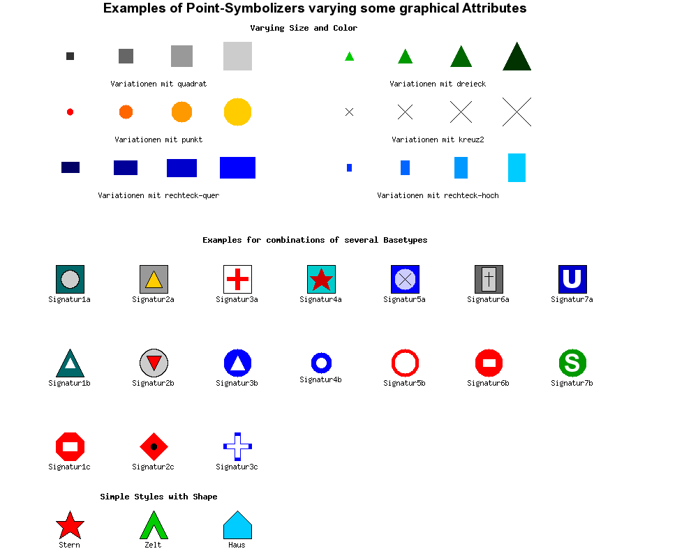
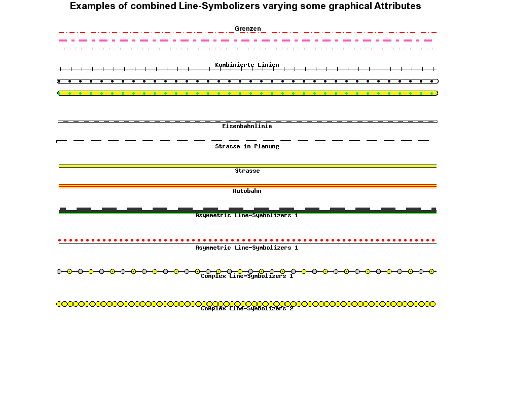
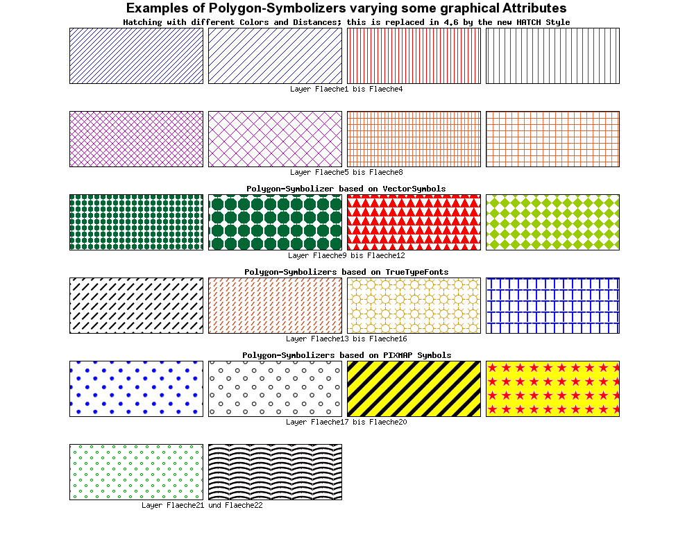
Basic Symbols
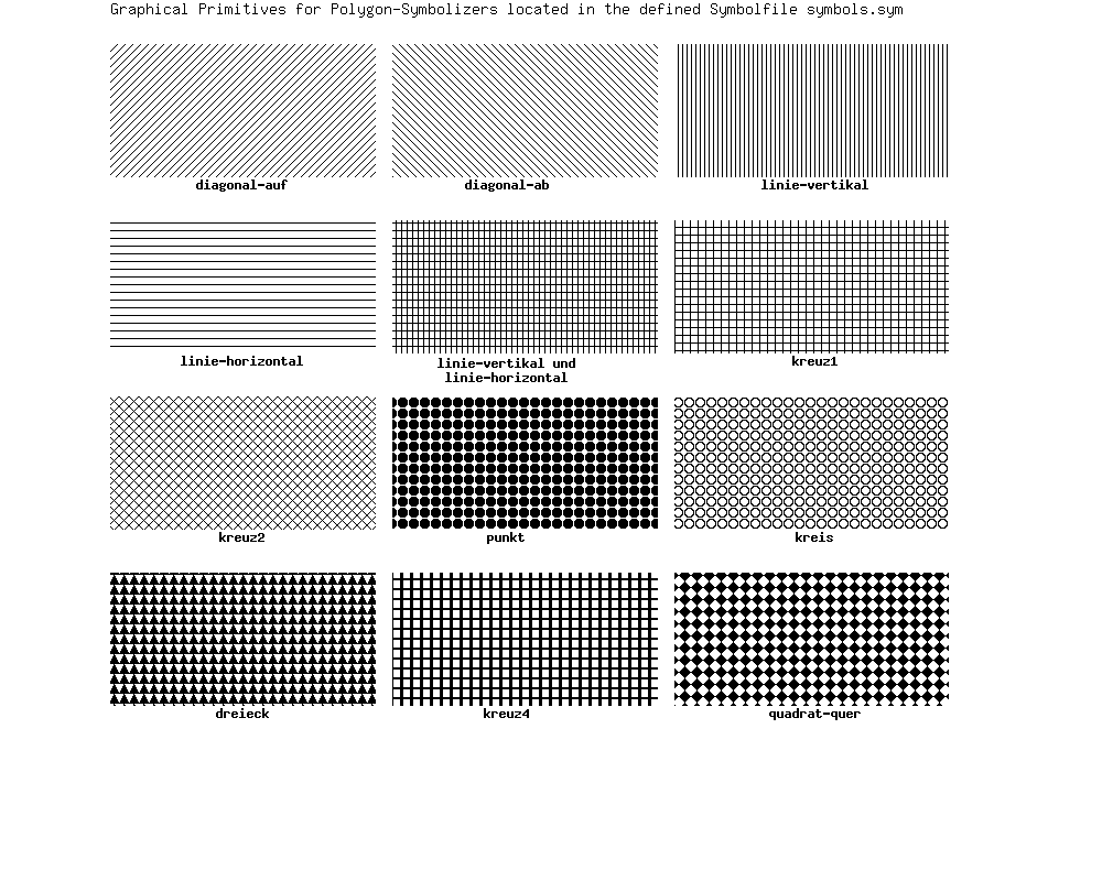
Complex Symbols
Tricks
Changing the center of a point symbol
MapServer does all transformations (offset, rotation) with respect to the symbol anchor point. By default, the anchor point is calculated from the symbol's bounding box. In some cases it can be useful to change the anchor point of a symbol. Since version 6.2, this can be done using the SYMBOL ANCHORPOINT.
Here are some examples of what can be achieved by using the ANCHORPOINT mechanisms for point symbols and decorated lines. There are three examples in the illustration, and each example shows the result with and without the use of ANCHORPOINT. At the top, arrows are added to lines using GEOMTRANSFORM start / end. In the middle, tags are added to lines using GAP and ANGLE. At the bottom, a point symbol is shifted and rotated. The red dots represent the center points, and the blue dots the offsets.
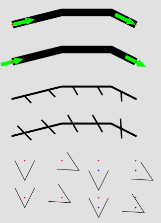
Shifting trick
Below you will find three tables that contain the SYMBOLs and the STYLE mechanisms that were used to generate the shifted symbols in the illustration.
SYMBOL
  NAME "arrow-start"
  TYPE vector
  FILLED true
  POINTS
    0 0.4
    3 0.4
    3 0
    5 0.8
    3 1.6
    3 1.2
    0 1.2
    0 0.4
  END # POINTS
  ANCHORPOINT 0 0.5
END # SYMBOL
SYMBOL
  NAME "arrow-end"
  TYPE vector
  FILLED true
  POINTS
    0 0.4
    3 0.4
    3 0
    5 0.8
    3 1.6
    3 1.2
    0 1.2
    0 0.4
  END # POINTS
  ANCHORPOINT 1 0.5
END # SYMBOL
|
LAYER  # Line
  STATUS DEFAULT
  TYPE LINE
  FEATURE
    POINTS
      20 80
      40 85
      60 85
      70 80
    END # Points
  END # Feature
  CLASS
    STYLE
      COLOR 0 0 0
      WIDTH 15
      LINECAP butt
    END # STYLE
    STYLE
      GEOMTRANSFORM "start"
      COLOR 0 255 0
      SYMBOL "arrow-start"
      SIZE 15.0
      ANGLE AUTO
    END # STYLE
    STYLE
      GEOMTRANSFORM "start"
      COLOR 255 0 0
      SYMBOL "circlef"
      SIZE 3
    END # STYLE
    STYLE
      GEOMTRANSFORM "end"
     COLOR 0 255 0
      SYMBOL "arrow-end"
      SIZE 15.0
      ANGLE AUTO
    END # STYLE
    STYLE
      GEOMTRANSFORM "end"
      COLOR 255 0 0
      SYMBOL "circlef"
      SIZE 3
    END # STYLE
  END # CLASS
END # LAYER
|
SYMBOL
  NAME "vert-line-shift"
  TYPE vector
  POINTS
    0 0
    0 10
  END # POINTS
  ANCHORPOINT 0.5 0
END # SYMBOL

SYMBOL
  NAME "vert-line"
  TYPE vector
  POINTS
    0 0
    0 10
  END # POINTS
END # SYMBOL
|
LAYER  # Line - symbol overlay
  STATUS DEFAULT
  TYPE LINE
  FEATURE
    POINTS
      20 50
      40 55
      60 55
      70 50
    END # Points
  END # Feature
  CLASS
    STYLE
      COLOR 0 0 0
      WIDTH 4
    END # STYLE
    STYLE
      COLOR 0 0 0
      SYMBOL "vert-line-shift"
      SIZE 20.0
      WIDTH 3
      ANGLE 30
      GAP -50
    END # STYLE
    STYLE
      COLOR 255 0 0
      SYMBOL "circlef"
      SIZE 3
      GAP 50
    END # STYLE
  END # CLASS
END # LAYER
|
SYMBOL
  NAME "v-line"
  TYPE vector
  POINTS
    0  0
    5  10
    10 0
  END # POINTS
END # SYMBOL

SYMBOL
  NAME "v-line-shift"
  TYPE vector
  POINTS
    0   0
    5  10
    10  0
  END # POINTS
  ANCHORPOINT 0.5 0
END # SYMBOL
|
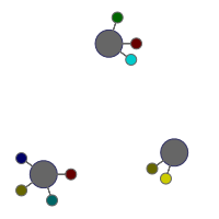
Shifting combined with rotation can also be used to good effect:
SYMBOL
  NAME "circle"
  TYPE ellipse
  POINTS
    1 1
  END # POINTS
  FILLED true
  ANCHORPOINT 0.5 0.5
END # SYMBOL

SYMBOL
  NAME "stick"
  TYPE vector
  POINTS
    -0.5 0.5
    0.5 0.5
    0.51223 0.42274
    0.54774 0.35305
    0.60305 0.29774
    0.67274 0.26223
    0.75 0.25
    0.82725 0.26223
    0.89694 0.29774
    0.95225 0.35305
    0.98776 0.42274
    1 0.5
    0.98776 0.57725
    0.95225 0.64694
    0.89694 0.70225
    0.82725 0.73776
    0.75 0.75
    0.67274 0.73776
    0.60305 0.70225
    0.54774 0.64694
    0.51223 0.57725
    0.5 0.5
    -0.5 0.5
  END # POINTS
  FILLED true
  ANCHORPOINT 0 0.5
END # SYMBOL
|
LAYER # Hole
  TYPE POINT
  STATUS DEFAULT
  FEATURE
    POINTS
      20 20
    END # POINTS
  END # FEATURE
  FEATURE
    POINTS
      80 30
    END # POINTS
  END # FEATURE
  FEATURE
    POINTS
      50 80
    END # POINTS
  END # FEATURE
  CLASS
    STYLE
      SYMBOL "circle"
      SIZE 25
      COLOR 102 102 102
      OUTLINECOLOR 51 51 102
    END
  END
END # layer

LAYER # Methods
  TYPE POINT
  STATUS DEFAULT
  PROCESSING "ITEMS=method"
  FEATURE
    POINTS
      20 20
    END # POINTS
    ITEMS "1"
  END # FEATURE
  FEATURE
    POINTS
      20 20
    END # POINTS
    ITEMS "5"
  END # FEATURE
  FEATURE
    POINTS
      20 20
    END # POINTS
    ITEMS "8"
  END # FEATURE
  FEATURE
    POINTS
      20 20
    END # POINTS
    ITEMS "13"
  END # FEATURE
  FEATURE
    POINTS
      80 30
    END # POINTS
    ITEMS "8"
  END # FEATURE

  ...

  CLASSITEM "method"
  CLASS
    EXPRESSION "1"
    STYLE
      SYMBOL "stick"
          SIZE 10
      COLOR 102 0 0
      OUTLINECOLOR 102 102 102
      ANGLE 0
    END # STYLE
      END # CLASS
  CLASS
    EXPRESSION "2"
    STYLE
      SYMBOL "stick"
      SIZE 10
      COLOR 204 0 0
      OUTLINECOLOR 102 102 102
      ANGLE 36
    END # STYLE
  END # CLASS

  ...

  CLASS
    EXPRESSION "14"
    STYLE
      SYMBOL "stick"
      SIZE 10
      COLOR 0 204 204
      OUTLINECOLOR 102 102 102
      ANGLE 324
        END # STYLE
  END # CLASS
END # layer
|
Current Problems / Open Issues
GAP - PATTERN incompatibility
Creating advanced line symbols involving dashed lines is difficult due to the incompatibility of the dashed line mechanisms (PATTERN) and the symbol on line placement mechanisms (GAP). If GAP could be a list instead of a single number (and perhaps renaming it to GAPS or DISTANCES), it would solve the issue, since we already have the INTIALGAP parameter (that specifies the distance to the first symbol on the line - added in version 6.2).
GAP - not full support for 2D
GAP does not support two dimensions (relevant for polygon fills), so the same gap will have to be used for for the x and the y directions. The introduction of new parameters - GAPX and GAPY could be a solution to this.
The End
We hope that this document will help you to present your data in a cartographically nice manner with MapServer and explains some basics and possibilities of the concept of MapServer as well as some weaknesses. It would be great to put together a cartographical symbols library for the profit of everyone. This especially concerns truetype fonts, which have been developed for some projects and contain some typical signatures for cartographical needs.
You can also view the discussion paper for the improvement of the MapServer Graphic-Kernel (German only).