


|
|
Home | Products | Issue Tracker | FAQ | Download |
|
|
| Author: | Håvard Tveite |
|---|---|
| Contact: | havard.tveite@nmbu.no |
Table of Contents
Geometry transformations return a new geometry. The purpose of a geometry transformation can be to achieve special effects for symbol rendering and labeling.
Geometry transformation is available at the LAYER level and the STYLE level. At the LAYER level (since 6.4), the original vector geometry (“real world” coordinates) is used. At the STYLE level, pixel coordinates are used.
It may be useful to apply pixel values also at the LAYER level, and that is possible. If UNITS is defined in the LAYER, the [map_cellsize] variable can be used to convert to pixel values at the LAYER level:
GEOMTRANSFORM (simplify([shape], [map_cellsize]*10))
The following simple geometry transformations are available at the CLASS STYLE level:
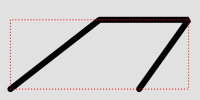
Geomtransform bbox
Class definitions for the example:
CLASS
  STYLE
    COLOR 0 0 0
    WIDTH 6
  END # STYLE
  STYLE
    GEOMTRANSFORM "bbox"
    OUTLINECOLOR 255 0 0
    WIDTH 1
    PATTERN 1 2 END
  END # STYLE
END # CLASS
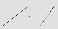
Geomtransform centroid
Style definitions for the example.:
STYLE
  GEOMTRANSFORM "centroid"
  COLOR 255 0 0
  SYMBOL circlef
  SIZE 5
END # STYLE
Symbol definition for the circlef symbol:
SYMBOL
  NAME "circlef"
  TYPE ellipse
  FILLED true
  POINTS
    1 1
  END # POINTS
END # SYMBOL
The direction of the line at the start / end point is available for rendering effects.
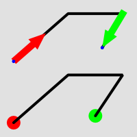
Geomtransform start and end usage
Class definitions for the example.
Lower part of the figure:
CLASS
  STYLE
    GEOMTRANSFORM "start"
    SYMBOL "circlef"
    COLOR 255 0 0
    SIZE 20
  END # STYLE
  STYLE
    COLOR 0 0 0
    WIDTH 4
  END # STYLE
  STYLE
    GEOMTRANSFORM "end"
    SYMBOL "circlef"
    COLOR 0 255 0
    SIZE 20
  END # STYLE
END # CLASS
Upper part of the figure:
CLASS
  STYLE
    COLOR 0 0 0
    WIDTH 4
  END # STYLE
  STYLE
    GEOMTRANSFORM "start"
    SYMBOL "startarrow"
    COLOR 255 0 0
    SIZE 20
    ANGLE auto
  END # STYLE
  STYLE
    GEOMTRANSFORM "start"
    SYMBOL "circlef"
    COLOR 0 0 255
    SIZE 5
  END # STYLE
  STYLE
    GEOMTRANSFORM "end"
    SYMBOL "endarrow"
    COLOR 0 255 0
    SIZE 20
    ANGLE auto
  END # STYLE
  STYLE
    GEOMTRANSFORM "end"
    SYMBOL "circlef"
    COLOR 0 0 255
    SIZE 5
  END # STYLE
END # CLASS
The startarrow symbol defintion (endarrow is the same, except for ANCHORPOINT (value for endarrow: 1 0.5):
SYMBOL
  NAME "startarrow"
  TYPE vector
  FILLED true
  POINTS
    0 0.4
    3 0.4
    3 0
    5 0.8
    3 1.6
    3 1.2
    0 1.2
    0 0.4
  END # POINTS
  ANCHORPOINT 0 0.5
END # SYMBOL
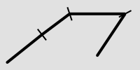
Geomtransform vertices
Class definitions for the example:
CLASS
  STYLE
    COLOR 0 0 0
    WIDTH 4
  END # STYLE
  STYLE
    GEOMTRANSFORM "vertices"
    SYMBOL "vertline"
    COLOR 0 0 0
    WIDTH 2
    SIZE 20
    ANGLE AUTO
  END # STYLE
END # CLASS
The vertline symbol definition:
SYMBOL
  NAME "vertline"
  TYPE vector
  POINTS
    0 0
    0 1
  END # POINTS
END # SYMBOL
The following simple geometry transformations are available at the LABEL STYLE level:
These are used for label styling (background colour, background shadow, background frame).
注解
The result of using labelpnt is affected by the LAYER LABELCACHE setting. If LABELCACHE is ON (the default), the label will be shifted when a non-zero sized symbol is added using labelpnt.
These transformations can be used to make background rectangles for labels and add symbols to the label points.
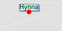
Geomtransform labelpnt and labelpoly
Class definitions for the example:
CLASS
  STYLE
    OUTLINECOLOR 255 255 204
  END # STYLE
  LABEL
    SIZE giant
    POSITION UC
    STYLE # shadow
      GEOMTRANSFORM "labelpoly"
      COLOR 153 153 153
      OFFSET 3 3
    END # Style
    STYLE # background
      GEOMTRANSFORM "labelpoly"
      COLOR 204 255 204
    END # Style
    STYLE # outline
      GEOMTRANSFORM "labelpoly"
      OUTLINECOLOR 0 0 255
      WIDTH 1
    END # Style
    STYLE
      GEOMTRANSFORM "labelpnt"
      SYMBOL 'circlef'
      COLOR 255 0 0
      SIZE 15
    END # Style
  END # Label
END # Class
Symbol definition for the circlef symbol:
SYMBOL
  NAME "circlef"
  TYPE ellipse
  FILLED true
  POINTS
    1 1
  END # POINTS
END # SYMBOL
A geometry transformation produces a geometry, and that geometry can be used as input to another geometry transformation. There are (at least) two ways to accomplish this. One is to combine basic geometry transformation expressions into more complex geometry transformation expressions, and another is to combine a geometry transformation expression at the LAYER level with a geometry transformation expressions or a simple geometry transformation at the CLASS STYLE level.
Combining geometry transformation expressions A geometry transformation expression contains a [shape] part. The [shape] part can be replaced by a geometry transformation expression.
For example:
GEOMTRANSFORM (simplify(buffer([shape], 20),10))
In this transformation, buffer is first applied on the geometry ([shape]). The resulting geometry is then used as input to simplify.
A style that demonstrates this:
STYLE
  GEOMTRANSFORM (simplify(buffer([shape], 20),10))
  OUTLINECOLOR 255 0 0
  WIDTH 2
END # STYLE
The result of this transformation is shown at the top of the following figure (red line). The original polygon is shown with a full black line and the buffer with a dashed black line.
Combining expressions with simple geometry transformations Simple geometry transformations are only avaiable for CLASS STYLE, but can be combined with geometry transformation expressions at the LAYER level.
Excerpts from a layer definitions that does this kind of combination:
LAYER
  ...
  GEOMTRANSFORM (simplify(buffer([shape], 10),5))
  CLASS
    ...
    STYLE
      GEOMTRANSFORM "vertices"
      COLOR 255 102 102
      SYMBOL vertline
      SIZE 20
      WIDTH 2
      ANGLE auto
    END # STYLE
  END # CLASS
END # LAYER
The result of this transformation is shown at the bottom of the following figure (the red lines). The result of the LAYER level geomtransform is shown with a full black line. The original polygon is the same as the one used at the top of the figure.
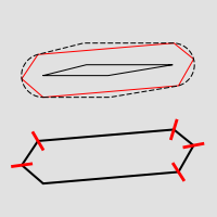
Combining geomtransform expressions
注解
Negative values for buffersize (setback) is not supported.
注解
Buffer does not seem to work for point geometries.
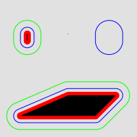
Geomtransform buffer
Some class definitions for the example.
Lower part (polygon with buffers):
CLASS
  STYLE
    OUTLINECOLOR 0 255 0
    GEOMTRANSFORM (buffer([shape], 20))
    WIDTH 1
  END # STYLE
  STYLE
    OUTLINECOLOR 0 0 255
    GEOMTRANSFORM (buffer([shape], 10))  #
    WIDTH 1
  END # STYLE
  STYLE
    COLOR 255 0 0
    GEOMTRANSFORM (buffer([shape], 5))  #
  END # STYLE
  STYLE
    COLOR 0 0 0
  END # STYLE
END # CLASS
Upper right part (layer level geomtransform):
LAYER  # line buffer layer
  STATUS DEFAULT
  TYPE LINE
  FEATURE
    POINTS
      80 70
      80 75
    END # Points
  END # Feature
  GEOMTRANSFORM (buffer([shape], 10))
  CLASS
    STYLE
      COLOR 0 0 255
    END # STYLE
  END # CLASS
END # LAYER
GEOMTRANSFORM generalize simplifies a geometry ([shape]) in a way comparable to FME’s ThinNoPoint algorithm. See http://trac.osgeo.org/gdal/ticket/966 for more information.
tolerance is mandatory, and is a specification of the maximum deviation allowed for the generalized line compared to the original line. A higher value for tolerance will give a more generalised / simplified line.
注解
Depends on GEOS.
The figure below shows the result of applying generalize at the STYLE level with increasing values for tolerance (10 - green, 20 - blue and 40 - red).
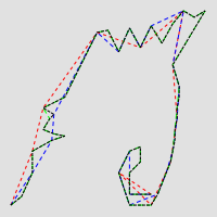
Geomtransform generalize
One of the STYLE definitions for the example (tolerance 40):
STYLE
  GEOMTRANSFORM (generalize([shape], 40))
  COLOR 255 0 0
  WIDTH 1
  PATTERN 3 3 END
END # STYLE
GEOMTRANSFORM simplify simplifies a geometry ([shape]) using the standard Douglas-Peucker algorithm.
tolerance is mandatory, and is a specification of the maximum deviation allowed for the generalized line compared to the original line. A higher value for tolerance will give a more generalised / simplified line.
The figure below shows the result of applying simplify at the STYLE level with increasing values for tolerance (10 - green, 20 - blue and 40 - red).
Geomtransform simplify
One of the STYLE definitions for the example (tolerance 40):
STYLE
  GEOMTRANSFORM (simplify([shape], 40))
  COLOR 255 0 0
  WIDTH 1
  PATTERN 3 3 END
END # STYLE
GEOMTRANSFORM simplifypt simplifies a geometry ([shape]), ensuring that the result is a valid geometry having the same dimension and number of components as the input. tolerance must be non-negative.
tolerance is mandatory, and is a specification of the maximum deviation allowed for the generalized line compared to the original line. A higher value for tolerance will give a more generalised / simplified line.
The figure below shows the result of applying simplifypt at the STYLE level with increasing values for tolerance (10 - green, 20 - blue and 40 - red).
Geomtransform simplifypt
One of the STYLE definitions for the example (tolerance 40):
STYLE
   GEOMTRANSFORM (simplifypt([shape], 40))
   COLOR 255 0 0
   WIDTH 1
   PATTERN 3 3 END
 END # STYLE
GEOMTRANSFORM smoothsia returns a smoothed version of a line.
The following parameters are used:
Example of a simple layer definition:
LAYER NAME "my_layer"
TYPE LINE
STATUS DEFAULT
DATA roads.shp
GEOMTRANSFORM (smoothsia([shape], 3, 1, 'angle'))
CLASS
  STYLE
    WIDTH 2
    COLOR 255 0 0
  END
END
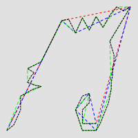
Here are some examples showing results with different parameter values.
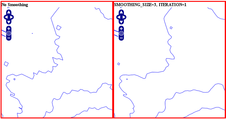
Original geometry (left) and smoothsia with default parameters (right)
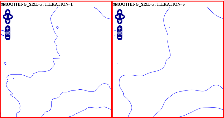
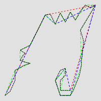
Smoothsia - Larger window size (left) and larger window size with more iterations (right)
smoothsia has several parameters that can be used to tune its behaviour. The following sections describe some cases / possiblities.
If you are trying to smooth a line that has a very high resolution (high density of vertices at the current view scale), you may not get the expected result because the vertices are too dense for the smoothing window size. In this case you might want to simplify the geometries before the smoothing. You can combine smoothing and simplification in a single geomtransform for that:
GEOMTRANSFORM (smoothsia(simplifypt([shape], 10)))
See RFC 89: Layer Geomtransform for more info. Here’s a visualization of the issue:
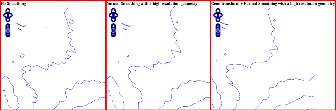
High resolution geometry, smoothing and simplification
If you are trying to smooth a long line that has a low density of vertices, you may not get the expected result in some situations. You may lose some important parts of the geometry during the smoothing, for instance around acute angles. You can improve the result by enabling a preprocessing step to add intermediate vertices along the line prior to smoothing.
This behavior is controlled using the all value in the preprocessing argument of the smoothsia geomtransform:
GEOMTRANSFORM (smoothsia([shape], 3, 1, 'all'))
This preprocessing will be performed before the smoothing. It adds 2 intermediate vertices on each side of each original vertex. This is useful if we really need to preserve the general shape of the low resolution line. Note that this might have an impact on the rendering since there will be more vertices in the output.
Here’s a visualization of the issue:
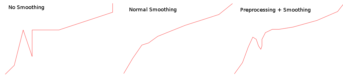
Effects of normal smoothing and preprocessing
The preprocessing step might not be appropriate for all cases since it can impact the smoothing result significantly. However, without it, you might notice bad smoothing for curved lines with large distances between the line vertices. See this example:
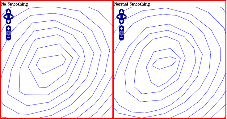
Effects of normal smoothing (without preprocessing)
You can improve that by enabling another type of preprocessing: angle. This one will add points at some specific places based on angle detection to recognize the curves. Here’s how you can enable it:
GEOMTRANSFORM (smoothsia([shape], 3, 1, 'angle'))
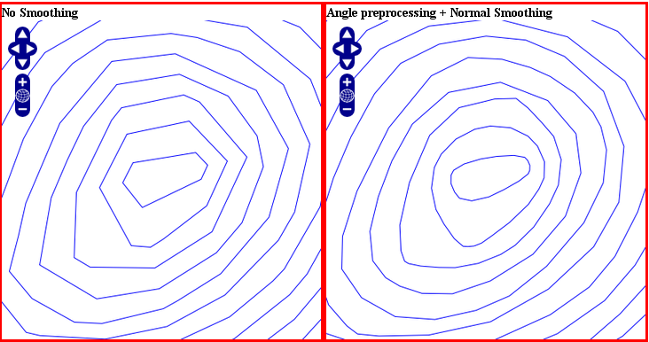
The use of angle with smoothsia